- 您现在的位置:买卖IC网 > Sheet目录393 > AMB315915 (Panasonic Electric Works)SENSOR REFL LONG V-TYPE
MA Motion Sensor (AMA1, AMB1, 2, 3)
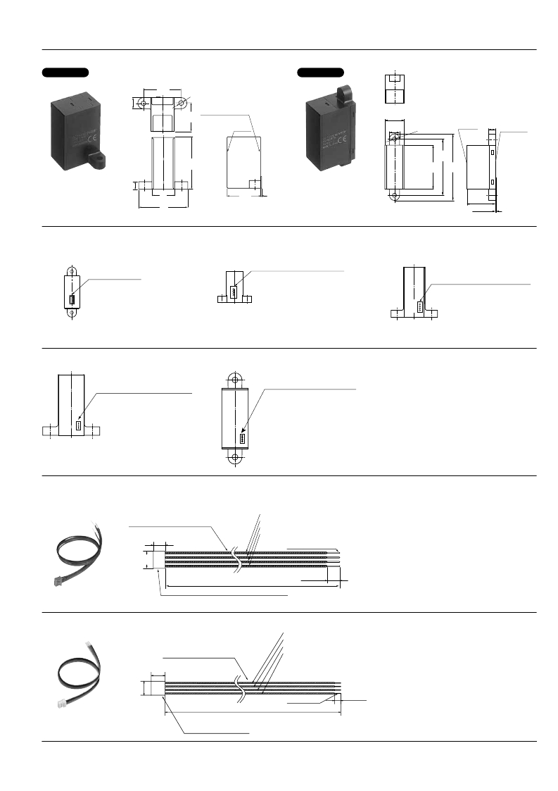
4. Long type (H type)
CAD Data
5. Long type (V type)
CAD Data
10
.394
33
1.299
4.2 dia.
.165 dia.
.276 Connector
24.7 Connector surface
.972 (Front lens surface)
Optical surface
20
.787
10
.394
4.2 dia.
.165 dia.
Optical
surface
7
surface
Receiver
Receiver
Projector
46
1.811
55
2.165
46 65
1.811 2.559
Projector
7
.276
20
.787
43
1.693
29.7
1.169 Max. 1
.039
29.7
1.169
MAX. 1
.039
WIRING DIAGRAM (Connector surface view)
1. Thin short type (V type)
2. Short type (H type)
IL-Z-4P-S125L3-E
3. Middle type (H type)
BM04B-SRSS
(J.S.T. Mfg. Co., Ltd.)
1: Output
2: GND
3: Power source
4. Built-in oscillation circuit type: N.C.
External triggering type:
external trigger input
1
2
3
4
(Japan Aviation Electronics Industry,
Limited)
1: Output
2: GND
3: Power source
4. Built-in oscillation circuit type: N.C.
External triggering type:
external trigger input
1
2
3
4
IL-Z-4P-S125T3-E
(Japan Aviation Electronics Industry,
Limited)
1: Output
2: GND
3: Power source
4. Built-in oscillation circuit type: N.C.
External triggering type:
external trigger input
4. Long type (H type)
5. Long type (V type)
1
2
3
4
IL-Z-4P-S125T3-E
(Japan Aviation Electronics Industry,
Limited)
1: Output
2: GND
3: Power source
4. Built-in oscillation circuit type: N.C.
External triggering type:
external trigger input
1
2
3
4
IL-Z-4P-S125T3-E
(Japan Aviation Electronics Industry,
Limited)
1: Output
2: GND
3: Power source
4. Built-in oscillation circuit type: N.C.
External triggering type:
external trigger input
OPTIONS (mm inch )
1. Connector with cable (for Short, Middle and Long type)
AMV9001
Lead wires AWG 28
4.3
.169
6.45
.254
1. Output (Black)
2. GND (Blue)
3. Power source (Brown)
4. Built-in oscillation circuit type: N.C.
External triggering type: external trigger input (Purple)
The edge is soldered
150 ± 5
5.906 ± .197
Socket housing IL-Z-4S-S125C3
(Japan Aviation Electronics Industry, Limited)
2. Connector with cable (for Thin short type)
4.5 ± 1
.177 ± .039
Note: Mistaken cable assembly can cause
damage to the internal circuits, so please
check the power cord before switching
ON. (Particular care must be taken as to
avoid reverse connection of the power.)
AMV9002
Lead wires UL 10368, AWG 30
5
.197
1. Output (Black)
2. GND (Blue)
3. Power source (Brown)
4. Start signal input (Purple)
5
.197
150 ± 5
5.906 ± .197
Solder coated
4.5 ± 2
.177 ± .079
Socket housing SHR-04V-S
ASCTB241E 201208-T
Panasonic Corporation
Automation Controls Business Unit
industrial.panasonic.com/ac/e/
发布紧急采购,3分钟左右您将得到回复。
相关PDF资料
AMHIRK-315AR3
RECEIVER RF MINI 315MHZ
AMHRR3-433
RECEIVER AM HYBRID 433MHZ
AMHRR30-433
RECEIVER AM MINI HYBRID 433MHZ
AML42SBC2
SWITCH INDICATOR COMPACT LED RED
AMS104Y
SENSOR LIGHT NAPICA 5V SMT 4SOP
AN101101
SENSOR MAGNET LINEAR ANGULAR POS
AN820032
SENSOR TLAPS WIRE VERSION 360DEG
AN920036
TLAPS SENSOR DL NO MAG 0-90 DEG
相关代理商/技术参数
AMB3401219
功能描述:工业移动感应器和位置传感器 MOTION SENSOR H TYPE 190CM DETECT DIST
RoHS:否 制造商:Honeywell 输出类型:Analog - Current 电压额定值:12 VDC to 30 VDC 线性:+/- 0.0011 % 温度范围:- 40 C to + 85 C 总电阻: 容差: 类型:Rotary Sensor
AMB34016
功能描述:工业移动感应器和位置传感器 MOTION SENSOR H TYPE 160CM DETECT DIST
RoHS:否 制造商:Honeywell 输出类型:Analog - Current 电压额定值:12 VDC to 30 VDC 线性:+/- 0.0011 % 温度范围:- 40 C to + 85 C 总电阻: 容差: 类型:Rotary Sensor
AMB3402
功能描述:工业移动感应器和位置传感器 6.5 TO 27V DC Long Type RoHS:否 制造商:Honeywell 输出类型:Analog - Current 电压额定值:12 VDC to 30 VDC 线性:+/- 0.0011 % 温度范围:- 40 C to + 85 C 总电阻: 容差: 类型:Rotary Sensor
AMB340203
功能描述:工业移动感应器和位置传感器 MOTION SENSOR H TYPE 30CM DETECT DIST
RoHS:否 制造商:Honeywell 输出类型:Analog - Current 电压额定值:12 VDC to 30 VDC 线性:+/- 0.0011 % 温度范围:- 40 C to + 85 C 总电阻: 容差: 类型:Rotary Sensor
AMB340204
功能描述:工业移动感应器和位置传感器 MOTION SENSOR H TYPE 40CM DETECT DIST
RoHS:否 制造商:Honeywell 输出类型:Analog - Current 电压额定值:12 VDC to 30 VDC 线性:+/- 0.0011 % 温度范围:- 40 C to + 85 C 总电阻: 容差: 类型:Rotary Sensor
AMB340205
功能描述:工业移动感应器和位置传感器 MOTION SENSOR H TYPE 50CM DETECT DIST
RoHS:否 制造商:Honeywell 输出类型:Analog - Current 电压额定值:12 VDC to 30 VDC 线性:+/- 0.0011 % 温度范围:- 40 C to + 85 C 总电阻: 容差: 类型:Rotary Sensor
AMB340206
功能描述:工业移动感应器和位置传感器 MOTION SENSOR H TYPE 60CM DETECT DIST
RoHS:否 制造商:Honeywell 输出类型:Analog - Current 电压额定值:12 VDC to 30 VDC 线性:+/- 0.0011 % 温度范围:- 40 C to + 85 C 总电阻: 容差: 类型:Rotary Sensor
AMB340207
功能描述:工业移动感应器和位置传感器 MOTION SENSOR 70CM DETECT DIST
RoHS:否 制造商:Honeywell 输出类型:Analog - Current 电压额定值:12 VDC to 30 VDC 线性:+/- 0.0011 % 温度范围:- 40 C to + 85 C 总电阻: 容差: 类型:Rotary Sensor
